Lighting
The lighting on the layout is all located on the Engine Shed. The shipyard itself had very little lighting so anything on the model has been added in the “heritage” phase. I did try some lamp standards but they didn’t really look right so I abandoned them and put them back into stock for another project.
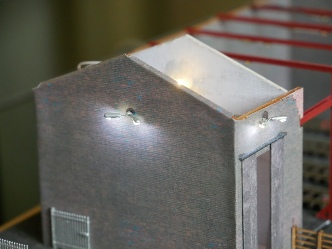
I’ve used two types of LED, both from Kytes Lights. On the outside of the shed are two of their Double LED Wall Lights whilst the interior lights (which won’t be seen) are the Prewired Nano 0603 LEDs in Warm White. The connecting wires on these are extremely fine so I decided to solder some slightly thicker wire on before they connect to the controller.
The LED lighting on the layout is controlled by a home-
The exterior lights and one
internal light in action
Fluorescent light effects, the final light has a failing starter
These may be reproogrammed later
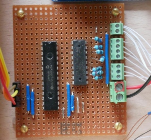
Although the MCP23017 has 16 outputs I only needed 8 for this job so I used a single 8 channel Darlington Pair chip. The layout is fairly self explanatory, the links to A0, A1 and A2 are to set the I2C address. I made one mistake, the 0.1” spacing screw terminals used for the lighting wires cannot be stacked together and I didn’t buy any 8-
The lights used require a resistor in line with the power supply to run on 12v, which I included on the control board. I used the suplied resistor values as starting point but experimented with higher values to get the effect I wanted. One thing to be noted is that this circuit switches on the 0v line not the 12v, however the resistors can be inserted in either.
Python Code
TBC
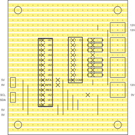
Stripboard layout for the
lighting controller
The actual controller board