Computer

As I wanted the computer to be mounted under the layout the only real option for me was a Raspberry Pi. These are great for this sort of job as there’s a huge infrastructure of add-ons and programming tips. The chosen model is a 3B+, that was the latest when I purchased it and it’s powerful enough for the job while not having the cooling issues of the later Pi 4.


I2C

I2C is a standard way of connecting peripherals to the computer. It’s a two wire connection and each add-on board has its own unique address, alterable in hardware. Boards that use this standard are readily available, you change the address on them typically by soldering links to pads. One thing you do need to watch though is that they’ll usually already have a base address dictated by the decoder chip, for example the controller used in my switching boards has a base address of 0x20 (that is 20 in hexadecimal, 32 in decimal) whilst the servo controller has a base address of 0x40; often you’ll then only have 3 links to make giving you a total of 8 addresses. Some boards, such as my I/O controller, will use more than one I2C address which further complicates the issue. I2C address 0x70 is used by the Pi for an internal MUX so is not available.


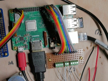
The Pi in situ
The HDMI and network cables are temporary, the USB dongle is for the keyboard

Peripheral

Base Address

Link Address

Board Address

Board Decimal

IO Controller, Bus 1

0x20

0x04

0x24

36

IO Controller, Bus 2

0x20

0x05

0x25

37

Lighting Switch

0x20

0x06

0x26

38

Servo Board

0x40

0x11

0x51

81

Pi System


0x70

112

Motor Controller

0x60

0x11

0x71

113

Each of these peripheral boards is discussed in more detail on other pages.

Pi IO

In the photo of the Pi you can see another home built interface board. This is to connect the reed switches for the train detection to the Pi’s built in I/O pins. There are enough available pins for this purpose, there wouldn’t have been enough for all the relays and lights hence the need for external interfaces.